
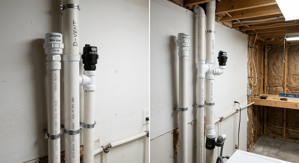
A plumbing drain vent system connects drain, waste, and vent (DWV) piping to the outside air so wastewater flows through the building without disrupting trap seals. Every fixture that discharges water into a drain line depends on a connected vent to admit air behind the moving wastewater. Without this air supply, drainage slows, gurgling occurs, and trap seals lose the water barrier that blocks sewer gas.
The DWV system performs two separate functions through connected but distinct piping. Drain and waste pipes carry wastewater and solid waste away from fixtures toward the building sewer. Vent pipes carry no wastewater; they carry air between the drainage system and the outdoor atmosphere. A vent pipe ties into the drain system above the fixture’s flood-level rim and typically terminates through the roof or, in specific configurations, through an exterior wall.
Plumbing codes in the United States, including the International Plumbing Code (IPC) and the Uniform Plumbing Code (UPC), regulate vent sizing, placement, and material to protect trap seals and control sewer gas migration into occupied spaces. Local jurisdictions adopt one of these model codes and apply amendments specific to climate, terrain, or existing infrastructure.
This article explains what plumbing vents are, how they function, the vent types recognized under U.S. plumbing codes, where vents are located in a structure, how individual fixtures are vented, applicable code requirements, installation steps, common vent-related problems, and how septic system venting differs from municipal sewer venting.
What Is a Plumbing Vent?
A plumbing vent is a pipe that connects the drain-waste-vent (DWV) system to the outdoor atmosphere to equalize air pressure inside the drainage piping. The vent allows air to enter the system as wastewater drains, which prevents the negative pressure that would otherwise siphon water out of fixture traps. Vent pipes carry air only; they do not carry wastewater under normal operating conditions.
A plumbing vent connects to the drainage system at a point above the fixture drain and extends upward, typically terminating above the roofline. The vent pipe diameter, height above the roof, and distance from the fixture trap are governed by plumbing code requirements that vary by fixture type and drainage fixture unit (DFU) load.
Plumbing Vent vs. Drain Vent vs. Vent Stack (Terminology)
“Plumbing vent,” “drain vent,” and “vent stack” refer to different components within the same venting system rather than interchangeable terms. “Plumbing vent” is the general term for any pipe that admits air into the DWV system. “Drain vent” commonly describes a vent connected directly to an individual fixture’s drain line, such as the vent serving a sink or toilet. “Vent stack” refers specifically to the primary vertical vent pipe that connects to the building drain or building sewer near its base and extends to open air, serving as the main air supply for multiple branch vents.
Plumbing professionals and code documents use these terms in overlapping ways depending on region and system configuration. A single-fixture bathroom may use only an individual vent connected to a stack vent, while a multi-story building relies on a dedicated vent stack to supply air to several floors of branch and individual vents simultaneously.
What Is a VTR (Vent Through Roof)?
A VTR (Vent Through Roof) is the section of vent pipe that penetrates the roof deck and terminates in open air above the structure. The VTR allows atmospheric air to enter the DWV system and allows sewer gas to exit above occupied living space, away from windows, doors, and mechanical air intakes.
Plumbing codes require a VTR to extend a minimum height above the roof surface, commonly 6 to 12 inches under the IPC and UPC depending on roof type and snow-load conditions in the jurisdiction. The termination point must maintain a minimum horizontal distance from windows, skylights, and air intakes, generally 10 feet, to prevent sewer gas from re-entering the building through ventilation openings. Roof flashing seals the pipe penetration to prevent water intrusion at the roof deck.
How Plumbing Vents Work
A plumbing vent works by admitting outdoor air into the drainage system, equalizing pressure ahead of and behind draining wastewater so trap seals remain intact. When a fixture discharges water, the moving water creates a pressure differential in the connected drain pipe. Without a vent, this differential draws air from the nearest available source, which is typically the water sealed in a downstream trap. The vent supplies that air directly from the atmosphere instead, protecting the trap seal.
The vent also allows sewer gases, including hydrogen sulfide and methane, to escape upward through the vent stack and VTR rather than accumulating within the drainage piping or migrating back through fixture traps into occupied space. Properly sized and positioned vents maintain atmospheric pressure at or near zero relative to the drainage system during normal fixture discharge.
Why Sewage Systems Need Venting
Sewage systems need venting to prevent trap-seal loss, slow drainage, and the buildup of sewer gas pressure within the piping network. A drain line without adequate venting experiences siphoning, where a draining fixture pulls water out of its own trap or a nearby fixture’s trap through negative pressure. An empty trap allows sewer gas to enter the building through the fixture drain opening.
Venting also equalizes pressure fluctuations caused by multiple fixtures discharging at the same time. Without sufficient vent capacity, positive pressure can build below a blockage or bend and force wastewater or gas back through a fixture drain, a condition known as blowback. Adequate vent sizing, based on the total drainage fixture units connected to the vent, controls both siphoning and blowback under normal use conditions.
Types of Plumbing Vents
Plumbing codes recognize several vent types, distinguished by their connection point, pipe path, and the fixtures they serve. The primary categories include the stack vent, wet vent, dry vent, common vent, circuit and loop vent, branch vent, relief vent, combination waste-and-vent system, and air admittance valve. Each type serves a specific configuration of fixtures and drainage layout permitted under the applicable code.
Selecting a vent type depends on fixture placement relative to the vent stack or stack vent, the number and type of fixtures sharing a vent, and the physical layout of the structure. Code officials evaluate proposed vent configurations against maximum distance, minimum diameter, and slope requirements before approving a drainage plan.
Vent Stack vs. Stack Vent
A vent stack and a stack vent differ in their connection point to the drainage system and their function within a multi-fixture building. A vent stack is a vertical pipe installed primarily to supply air circulation to one or more drain stacks, connecting to the building drain near its base independent of any single fixture’s trap arm. A stack vent is the extension of a soil or waste stack above the highest fixture drain connection, carrying no wastewater and functioning as the vent termination for that stack.
A single-story structure with one bathroom group often uses only a stack vent, since one stack serves as both drain and vent above the top fixture connection. A multi-story building typically requires a separate vent stack connected near the base of the drainage stack to maintain adequate air circulation across all floors.
Wet Vent
A wet vent is a pipe that serves as a drain for one fixture and a vent for another fixture connected to the same branch. Plumbing codes permit wet venting when fixture unit loads, pipe diameter, and slope fall within specified limits, allowing a single pipe to carry both wastewater and vent air at different points in its length.
Wet venting reduces the total pipe footage needed in a bathroom group by allowing a lavatory, for example, to vent a bathtub or shower connected downstream on the same horizontal branch. The IPC and UPC set maximum fixture unit loads and minimum pipe diameters for wet-vented systems, and the wet-vented section must maintain a minimum slope toward the drain without exceeding the maximum slope permitted for vent function.
Dry Vent
A dry vent is a vent pipe that carries only air and never carries wastewater under any operating condition. Dry vents connect above the flood-level rim of the fixtures they serve and slope upward toward the vent stack or stack vent, preventing any wastewater from entering the vent piping.
Dry venting represents the most common vent configuration for individually vented fixtures. Codes require dry vent pipes to maintain a continuous upward slope from the fixture connection to the vent stack, with no low points capable of trapping water or debris that would restrict airflow.
Common Vent
A common vent is a single vent pipe that serves two fixture drains connected at the same level or at different levels within the same vertical piping run. Plumbing codes permit common venting when both fixtures connect to the drainage system at approximately the same point, such as back-to-back lavatories on opposite sides of a wall.
Common venting reduces the number of individual vent pipes required in a multi-fixture installation. The connection point, pipe size, and fixture unit load for a common vent must meet the same code limits that apply to a single dry vent serving the combined fixture unit load of both connected fixtures.
Circuit and Loop Vents
Circuit and loop vents serve a battery of similar fixtures, such as a row of floor drains or sinks, through a single horizontal vent pipe connected ahead of the last fixture connection on the branch. A circuit vent connects to a horizontal branch drain serving two or more traps and extends to the vent stack or stack vent without connecting to any additional fixture between its origin and termination. A loop vent performs a similar function but connects back to a stack vent rather than a separate vent stack.
Circuit and loop vents apply primarily to commercial installations with multiple fixtures arranged in a row, such as restroom batteries in public buildings. Code-specified relief vents may accompany circuit and loop vent installations when the fixture unit load exceeds specified thresholds.
Branch Vent
A branch vent is a vent pipe that connects one or more individual vents to a vent stack, stack vent, or common vent. Branch vents distribute air from the main vent piping to individual fixture vent connections throughout a floor or fixture group.
A branch vent must maintain the minimum pipe diameter required for its connected fixture unit load and connect to the vent stack at a point above the highest fixture drain served by that branch, or as otherwise permitted under the applicable plumbing code.
Relief Vent
A relief vent is an auxiliary vent connected to a drainage stack to provide additional air circulation and pressure relief when the primary vent stack alone cannot adequately serve the fixture unit load. Codes require relief vents on drainage stacks exceeding specified height or fixture unit thresholds, and on horizontal branches serving circuit or loop-vented fixture batteries.
Relief vents connect between the drainage stack and the vent stack at intervals specified by code, typically every fifth floor or story in tall buildings, to prevent excessive pressure fluctuation within the stack during peak fixture use.
Combination Waste-and-Vent System
A combination waste-and-vent system is an engineered drainage configuration in which an oversized, minimally sloped horizontal drain pipe serves as both the waste line and the vent for fixtures that lack sufficient space for conventional individual venting. This system applies primarily to floor drains, standpipes, and island sinks where a dry vent cannot reasonably connect to a vent stack above the fixture.
Plumbing codes require a licensed design professional’s approval for combination waste-and-vent installations, along with specific pipe sizing, slope limits, and a connected dry vent at the far end of the system to supply air circulation.
Plumbing Vent Diagram and Anatomy
A plumbing vent diagram shows the vertical and horizontal piping that connects each fixture drain to the vent stack and, ultimately, to the vent termination above the roof. The core components of the venting anatomy include the fixture trap, trap arm, individual or branch vent, vent stack, stack vent, and VTR.
The trap arm carries wastewater from the fixture trap to its connection with the drain stack, and the vent connects to the drainage system within the maximum distance permitted between the trap weir and the vent connection, a limit that varies by pipe diameter and fixture type. The vent stack rises from its connection point at or near the base of the building drain to a point above the highest fixture, where it typically joins the stack vent before terminating through the roof as a VTR. Cleanouts, located at changes in direction and at set intervals along the drain piping, provide access for inspection and clearing without disrupting the vent path.
Where Are Plumbing Vents Located?
Plumbing vents are located wherever a fixture drain connects to the DWV system, with the vent pipe routed upward through walls, floors, and the roof structure to reach open air. Vent placement depends on the fixture’s position within the building, the layout of interior walls, and the routing of the main drainage stack.
Most vent terminations occur above the roofline, though code-permitted alternatives allow certain vents to terminate through an exterior wall or connect to a mechanical air admittance valve within an accessible interior space when a roof penetration is impractical.
Roof and Attic Venting
Roof and attic venting routes vent pipes vertically through the attic space to a termination point above the roof deck, protected by roof flashing at the penetration. This is the most common vent path in residential construction, since it allows a single stack to serve fixtures on multiple floors before exiting through the roof.
In cold climates, codes require increased vent pipe diameter near the roof terminal to reduce the risk of frost closure, where condensation and frost narrow or block the vent opening during freezing conditions. Attic-routed vents must maintain adequate clearance from structural framing and insulation to prevent physical damage or restricted airflow.
Wall and Side-of-House Venting
Wall and side-of-house venting terminates the vent pipe through an exterior wall rather than the roof, typically using an air admittance valve or a code-approved horizontal vent termination fitting. This configuration applies most often to additions, remodels, or fixtures located far from the existing vent stack, where routing a vent through the roof is structurally impractical.
Codes place strict limits on wall-terminated vents, including minimum height above grade, minimum distance from windows and doors, and restrictions on the direction the vent opening faces to prevent sewer gas from entering adjacent spaces.
Under-Sink Venting
Under-sink venting refers to a vent connection or air admittance valve installed within the cabinet space beneath a sink, most often used for island sinks or remodeled fixtures that cannot connect to a conventional vent stack. An air admittance valve mounted under the sink admits air into the drain line during discharge and seals when not in use, eliminating the need for a pipe run to the roof for that fixture.
Local code adoption determines whether under-sink air admittance valves are permitted, since some jurisdictions restrict or prohibit mechanical vents in place of open-air venting.
Plumbing Vents by Fixture
Each plumbing fixture connects to the drainage system through a vent sized and positioned according to that fixture’s drainage fixture unit (DFU) rating, trap size, and location relative to the vent stack. Toilets, kitchen sinks, bathroom sinks, showers, bathtubs, and floor drains each carry distinct venting requirements based on their typical discharge volume and trap configuration.
Fixture-specific vent sizing and critical distance limits, which govern the maximum allowable distance between a fixture trap and its vent connection, are set by the applicable plumbing code and vary based on the fixture’s trap arm diameter.
Toilet Venting
Toilet venting requires a minimum 2-inch vent pipe connected to the closet bend or drain line within the code-specified critical distance, which is commonly up to 6 feet for a 3-inch trap arm under the IPC. Toilets carry the highest fixture unit rating among common residential fixtures, typically 4 DFU, requiring correspondingly larger vent and drain piping compared with sinks or bathtubs.
A toilet’s vent connects above the trap weir and routes to the nearest vent stack, stack vent, or wet-vented branch serving the bathroom group, subject to the fixture unit and distance limits set by the adopted code.
Kitchen Sink Venting
Kitchen sink venting requires an individual or common vent connected to the sink drain, sized according to the fixture unit load of the sink and any connected disposal or dishwasher. A single-compartment kitchen sink typically carries a 2 DFU rating, while a double-compartment sink with a garbage disposal may require additional fixture unit allowance under the applicable code.
Where a code prohibits or restricts air admittance valves, kitchen sinks located away from an exterior wall or existing stack commonly use a wet-vented or combination waste-and-vent configuration to avoid extensive pipe routing.
Bathroom Sink Venting
Bathroom sink venting connects a 1.25-inch or 1.5-inch trap arm to an individual, common, or wet vent, reflecting the sink’s typical 1 DFU rating. Bathroom sinks frequently serve as the wet-vent source for an adjacent bathtub or toilet within the same bathroom group, provided the combined fixture unit load and pipe sizing meet code limits.
The critical distance between a bathroom sink trap and its vent connection is shorter than for larger-diameter fixtures, requiring the vent tie-in to occur close to the fixture drain when a 1.25-inch trap arm is used.
Shower and Bathtub Venting
Shower and bathtub venting connects a 1.5-inch or 2-inch trap arm to an individual or wet vent, with a typical fixture unit rating of 2 DFU. Showers and bathtubs are commonly wet-vented through an adjoining bathroom sink drain when the fixtures share the same wall or floor cavity and the combined fixture unit load remains within code limits.
Combination shower-bathtub units follow the same trap and vent sizing requirements as a standalone bathtub, since the drainage fixture unit rating reflects the shared trap and drain connection.
Floor Drain Venting
Floor drain venting requires an individual, common, circuit, or combination waste-and-vent connection sized for the floor drain’s fixture unit rating, which varies based on the drain’s connected trap size and expected use. Floor drains in mechanical rooms, basements, and commercial kitchens frequently rely on circuit venting or a combination waste-and-vent system when multiple floor drains share a single horizontal branch.
Floor drain traps require a trap primer or adequate use frequency to maintain the trap seal, since infrequent use allows the trap water to evaporate even when the vent functions correctly.
Plumbing Vent Codes and Requirements
Plumbing vent codes and requirements govern vent pipe material, minimum diameter, maximum critical distance, roof termination height, and minimum clearance from windows, doors, and air intakes. The IPC and UPC set baseline requirements, and local jurisdictions may adopt amendments that adjust specific dimensions for climate, seismic activity, or existing housing stock.
Vent pipe material is limited to types approved for DWV use, including PVC, ABS, cast iron, and copper, matched to the material used in the connected drainage piping in most jurisdictions. Minimum vent pipe diameter is generally not smaller than 1.25 inches for individual fixture vents, increasing based on the fixture unit load carried and the length of the vent run. Vent terminations must extend a minimum height above the roof surface and maintain a minimum horizontal distance, commonly 10 feet, from any window, door, or air intake opening. A permit and inspection are typically required before a new or altered vent system is enclosed within finished walls or ceilings.
How to Vent a Plumbing Fixture
To vent a plumbing fixture, determine the fixture’s drainage fixture unit (DFU) rating and trap arm diameter, identify the nearest available vent stack or stack vent, and connect a vent pipe within the code-specified critical distance from the trap weir. Confirm local code adoption (IPC, UPC, or a jurisdiction-specific amendment) before selecting a vent configuration, since permitted vent types and distances vary between codes.
Route the vent pipe upward from its connection point, above the fixture’s flood-level rim, maintaining a continuous upward slope toward the vent stack with no low points that could trap water. Select the minimum vent pipe diameter required for the fixture’s DFU load and the total fixture units carried by the branch or stack the vent connects to. Install the vent connection using a wye or combination wye-and-eighth-bend fitting rather than a sanitary tee, since code prohibits venting connections that could allow wastewater to enter the vent path. Secure all pipe joints according to the material manufacturer’s specifications, and schedule a rough-in inspection before enclosing the vent piping within walls or ceilings.
Common Plumbing Vent Problems
Common plumbing vent problems include blocked vent terminations, undersized vent piping, disconnected or damaged vent sections, and improperly installed air admittance valves. A blocked VTR, caused by debris, bird nests, ice, or frost closure, restricts airflow into the drainage system and produces symptoms similar to a completely unvented fixture, including slow draining and gurgling sounds.
Undersized or improperly routed vent piping, often the result of unpermitted remodeling work, fails to supply adequate air during peak fixture use, resulting in trap-seal loss and sewer gas odor inside the building. A cracked or disconnected vent pipe within a wall or attic space allows sewer gas to escape into the structure rather than venting through the roof, and this type of failure frequently goes undetected until an odor or inspection reveals the disconnection. A malfunctioning air admittance valve that fails to open under negative pressure produces the same siphoning symptoms as a fully blocked vent, since the valve is not supplying replacement air to the drain line.
Septic System Venting
Septic system venting equalizes air pressure within the household drainage system connected to a septic tank, using the same vent stack, branch vent, and VTR components required for a municipal sewer connection. A septic-connected building requires the identical fixture-level venting described under plumbing vent codes, since the vent’s function, protecting trap seals and releasing sewer gas, applies regardless of the wastewater treatment method downstream.
Septic tanks themselves typically include a separate tank vent or rely on the household plumbing vent stack, combined with a soil absorption field designed to allow gas exchange through the surrounding soil, to manage gases generated by anaerobic digestion within the tank.
How Septic Venting Differs From Sewer Venting
Septic venting differs from sewer venting in that a septic system adds tank-level gas management to the standard household vent stack, while a municipal sewer connection relies solely on the building’s vent stack and the municipal collection system’s own venting. A septic tank produces higher concentrations of methane and hydrogen sulfide through anaerobic digestion than a directly sewered connection, since wastewater retains longer within the tank before discharging to the drain field.
Some septic system designs include a dedicated tank vent riser or rely on the soil absorption field’s gas-permeable cover material to release excess tank gas, in addition to the household VTR required for fixture-level venting. Local health department regulations governing septic system design, separate from the plumbing code governing household vent sizing, determine whether a dedicated tank vent is required in a given jurisdiction.